
A lathe turns cylindrical geometry from bar or from a chucked blank, and the tolerance reality of the work depends on which kind of lathe, which features, and which material are in the picture. The diameters, the bores, the lengths, and the threads each behave differently, and the machine class — a two-axis lathe, a live-tool machine, a Swiss-type, a multi-spindle — decides how many of those features can be produced in one setup. This guide maps what tolerances and surface finishes are realistic on CNC lathe machining, feature by feature, so the round part on the drawing matches the round part the process can actually hold.

What tolerance can a CNC lathe realistically hold?
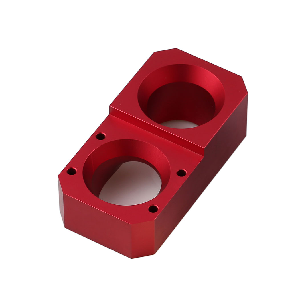
On a capable CNC lathe, turned diameters and shoulders hold ±0.002 mm as the practical production standard, with process capability demonstrated at Ppk ≥ 1.67 at the initial study on the key characteristics. That band covers the features the lathe produces in one setup from a stable bar or a rigid chucked blank: the external diameters, the internal bores cut with a boring bar, the lengths to the shoulders, and the groove positions. The band is the repeatable production number, the value you design to and a supplier verifies across a run. Features that need more leave the lathe for grinding, and features that a two-axis lathe cannot reach go to a live-tool machine or a secondary operation.
The band depends on the rigidity of the setup. Bar-fed work through a guide bushing is stable and repeats; long slender bars deflect and chatter, and the diameter band on a long unsupported section loosens regardless of the machine's capability. A chucked blank is rigid but adds the chucking error on the first cut and the re-chucking error if the part must be turned from the other end. Ask the supplier which features are cut from the bar and which require a second operation, because the band across the two is set by the relocation, not by the lathe. The honest tolerance quote names the setup boundary as well as the machine.
How do external diameters, bores, and lengths behave differently on a lathe?
Each class of turned feature carries its own process story. External diameters are the lathe's home ground: the OD is cut by a turning tool against the bar or the chuck, the tool is rigid, and the band holds tight with a stable setup. Internal bores are cut by a boring bar, which is less rigid the deeper it reaches, so bore size and roundness are set by the bar's stiffness and the depth of the bore; a deep small-diameter bore is a real tolerance challenge, not a routine cut. Lengths to shoulders are controlled by the tool position and the part's axial location, and they hold well when the datum face is cut in the same setup. Each feature class deserves its own tolerance thought rather than a blanket band.
The relationships between the classes are where the drawing usually matters most. Concentricity between an OD and a bore cut in one setup is strong, because both features are cut about the machine's axis; concentricity between a bore cut from one end and an OD cut after re-chucking depends on the re-location accuracy. Squareness between a turned face and the axis is set by the tool geometry and the setup. Ask the supplier to name which features are cut in which clamping and how the critical relationships are protected. The supplier that sequences the setups so the datum features are cut first, and holds the critical relationships inside one clamping, is the supplier whose tolerances are a plan rather than a hope.
What is realistic on lathe-cut threads?
Threads are a lathe speciality, and their realism is stated in classes rather than microns. A thread cut on a lathe is verified against a thread gauge for its class, with the pitch diameter measured for the fit; the class the drawing calls out should match the function the thread serves, because a class that is too tight for the application adds gauging cost and rejection risk without improving the part. External threads are cut with a single-point tool or a thread chase, and internal threads with a tap or a single-point boring-bar tool; the method sets the surface and the accuracy of the thread flank. On production work, thread rolling is an alternative that improves the surface and the fatigue strength of the thread root, at the price of a rolling head setup.
The thread callout should name the class, the pitch, and the gauge or measurement the part will be checked against, because thread verification is as much a part of the tolerance story as the machining. A drawing that says only "M12 thread" leaves the class and the verification open; one that names the class, the fit, and the inspection method gets a part whose threads are known to work. Ask the supplier how internal threads are verified on small or deep holes, where standard plug gauges may not reach, and how the pitch diameter is measured on the production lot. The thread that is specified and verified as a system is the thread that does not fail at assembly.
How does the lathe class change what tolerance is realistic?
The machine class decides how much of the part can be made in one setup, and the setup count decides the tolerance between features. A two-axis lathe turns diameters and faces; it cannot mill, and features on the side of the part require a second machine or a second operation. A lathe with live tooling — a mill-turn machine — adds rotating tools that drill cross-holes, mill flats and hexes, and cut slots while the part is still in the spindle, holding those features to the turned datum in the same clamping. A Swiss-type lathe guides the bar through a bushing close to the work, which is how long, slender, precisely concentric parts are held. A multi-spindle machine runs several parts at once, which is a volume play rather than a tolerance play.
For you the practical question is whether the drawing's features fit the machine class that will quote them. A part with cross-holes and flats is a mill-turn part, and quoting it to a two-axis shop means secondary operations and a datum hand-off. A long slender shaft with tight concentricity is a Swiss-type part, and quoting it to a conventional lathe means fighting deflection. The quote should name the machine class behind each feature group, and you should read that naming as the first signal of whether the supplier has matched the process to the geometry. The drawing that is routed to the right lathe class is the drawing whose tolerances are held rather than argued.
What surface finish is realistic from lathe turning?
Surface finish on a turned part is set by the feed rate, the tool nose radius, and the stability of the cut, and the relationship is predictable enough to design to. A smaller feed leaves a finer surface; a larger nose radius spreads the cut and smooths the surface; and both work only while the cut stays stable, because chatter and built-up edge destroy any finish the parameters promise. A standard turning pass leaves a finish that suits most general faces. A controlled finishing pass brings functional faces lower, toward the Ra 0.8 µm range that seals, bearing fits, and polished-appearance faces carry. On short, rigid features a well-set-up finish pass can go lower still, but the production repeatability of the surface falls as the process window narrows.
The honest rule on turned finishes is to ask which values are produced by the standard cycle and which require a special pass or a process change. A finish that is part of the standard cycle repeats across the lot; one that requires a nursed finishing pass on every part adds cycle time, tool cost, and the risk that the lot drifts. A very fine surface on a turned part usually means grinding, because grinding holds the finish and the roundness together in a way that a turning pass on production cannot match. When a drawing calls a very fine Ra on a long or slender turned feature, the honest conversation is about moving the feature to grinding, because the turning pass will deflect before it produces a mirror.
How do material and geometry set the limits on lathe work?
Material sets the process window before the machine runs. Free-cutting grades turn fast, hold size, and finish cleanly, which is why they dominate turned-part design. The gummy and work-hardening alloys fight the finish and the size control on the finishing pass, and the heat-retentive grades hold heat in the cut, attack the tool edge, and limit both the finish and the dimensional stability of the part as it heats and cools. Bar condition matters as much as grade: a straight, round bar in the right condition feeds and cuts predictably, while a bar that is out of round or not straight produces parts whose diameters and concentricity wander no matter how the machine is set.
Geometry interacts with material on the features that define turned parts. Long slender shafts deflect under the cutting force, and a tight band or a fine finish on a slender section is a fight against the deflection. Thin-wall tubes and sleeves are flexible and can chatter; the bore and the OD of a thin-wall part move together, and cutting one side affects the other. Deep internal bores limit the boring bar by reach and stiffness. The design that keeps the critical diameters, finishes, and concentricity on short, rigid, well-supported sections is the design that gets them held; the drawing that puts the tight band on the slender, unsupported length produces the first-article argument every time.
When do grinding and secondary operations finish what the lathe started?
Grinding finishes what the lathe cannot hold: the ±0.002 mm band, the very fine finishes, and the roundness requirements that turning cannot repeat across a run. A bearing journal or a seal seat is typically turned to near-net and then ground to its final band, because grinding holds the size and the roundness together. Secondary machining on a turned part — cross-drilling, milling a hex or a slot, broaching a keyway — is done on a mill-turn machine in the same clamping or on a secondary machine afterwards, with the feature position held to the turned datum. Surface treatment on turned parts adds its own process logic: stainless is passivated after machining to remove free iron, and plated or anodized features are machined to the dimension that the coating thickness will bring to final size.
For you the rule is to ask which process produces each critical feature and how the datum is held between the processes. A part that is turned, then ground on a journal, then milled for a hex is three processes and one datum chain, and the chain holds only when one quality system manages all three. When the supplier runs the processes internally, the relationships are held in one inspection loop; when the work goes out, each hand-off is a place where the tolerance story can break. The drawing that routes each feature to the process that can actually produce it, and sends it to a supplier that runs those processes under one roof, is the drawing that gets made as specified.
How should you specify and verify tolerances on a lathe-turned part?
A lathe-turned drawing should state its defaults and its critical features separately. The general tolerance class governs the uncalled diameters and lengths; the critical features carry their own bands; the threads name their class and their verification; the finishes sit on the functional faces with the function named where the surface must seal or bear; and the material line names the bar grade and condition. The drawing should also flag which relationships matter across setups, so the supplier sequences the work to protect them. A drawing that states its defaults and its critical relationships is a drawing that quotes and machines consistently.
Then verify at the first article and through the run. The dimensional report should show the diameters, bores, lengths, and concentricity values with the instruments named; the threads should be checked against their gauges; the finishes should be read on a profilometer; and the capability data should show the key characteristics at Ppk ≥ 1.67 initial. When a value sits near its band edge on the first article, ask how the process will be adjusted before the lot runs, because a band-edge reading is a warning that the lot will drift. The drawing that calls out honestly, the supplier that measures honestly, and the buyer that reviews the data are the three legs of a lathe tolerance program that holds across the run.
What this shop actually runs
Capability evidence should come as specifics, not slogans. Behind this guide is a 6,800 m2 plant in Dongguan, China running 100+ CNC machines with 100+ staff. The machine list by category:
- 5-axis machining centres (10+) - Mazak VARIAXIS I-600 (510/910/510 mm travel, 12,000 rpm, 22 kW, 71.6 N·m, 30-tool BT40) and Mazak INTEGREX I-250H S (B-axis 0.0001°, 24 kW, 124 N·m, 38-tool HSK-A63). Intended for compound-angle parts, single-setup multi-face prismatic work, and aerospace fittings where datum transfer loss is unacceptable.
- 3-axis / 4-axis machining centres (50+) - Brother SPEEDIO S500Z2N / S700Z2N (10,000 rpm, 14/21-tool ATC, 0.7 s tool-to-tool, Z-axis 2.2 G) and Mazak VCE-430A L / VCE-570C L (10,000 rpm, 118 N·m, 24-tool ATC). Intended for prismatic parts, plates, brackets, housings.
- Swiss-type turning centres (10+) - Citizen Cincom A20-3F7 (Φ20 mm, 10,000 rpm), TSUGAMI B0206-III / B0205-III (Φ20 mm, 0.1 µm), STAR SR-32JII / SR-32J Type N (Φ32 mm, 8,000 rpm). Intended for long, slender rotational parts at ±0.002 mm.
- CNC turning centres (20+) - HEADMAN T70M/1250 (720 mm swing, 117 mm bore, 3,000 rpm, BMT75 12-station turret). Intended for shafts, bushings, flanges up to ±0.002 mm.
- Wire EDM (5+) - Sodick AQ535L (550/350/300 mm travel, ±20° taper, 800 kg workpiece). Intended for hardened tool steel, internal splines, sharp internal corners that milling cannot reach.
- Inspection: Hexagon CMM + 20+ gauges - Hexagon CMM for coordinate measurement, plus vision system, profilometer, hardness tester, coating thickness gauge, XRF for material verification. The 10:1 rule (gauge 10x more accurate than the band) is applied to every feature.
- Machine highlights - VARIAXIS I-600: one-setup multi-face 5-axis + MAZA-CHECK auto-calibration; INTEGREX I-250H S: DONE-IN-ONE mill-turn, B-axis 0.0001° + Ai thermal shield; SPEEDIO S500Z2N / S700Z2N: Z-axis 2.2 G + 0.7 s ATC; Swiss-type: guide-bush switchable + 0.1 µm resolution.
Tolerance: ±0.003 mm CNC milling / ±0.002 mm CNC turning / ±0.002 mm grinding and wire EDM. Capability: Ppk >= 1.67 initial on key characteristics, Cpk >= 1.33 ongoing.
Certificates: ISO 9001:2015 (116024/A/0001/UK/En), IATF 16949:2016 (131941/A/0001/SM/En, with design clause 8.3 excluded, stated openly) and ISO 14001:2015 (116024/B/0001/UK/En), issued to Dongguan Zhuohang Ltd, registration 91441900MA4UWT6X39, founded 2005.
Where we ship: Austria, Belgium, the Czech Republic, Denmark, France, Germany, Greece, Hungary, Ireland, Italy, the Netherlands, Spain, Sweden and the United Kingdom in Europe; Brazil, Canada, Mexico and the United States in the Americas; China, Israel, Japan, Singapore and Sri Lanka in Asia; Australia and New Zealand in Oceania; and South Africa in Africa — plus other countries and regions worldwide, shipped from our base in Dongguan, China.
Contact: Felipe Iglesias, [email protected], +86 13126536955.
Need a tolerance and finish plan for a lathe-turned part?
Send the drawing with the critical callouts through the services page — the review will name the machine class, the process behind each diameter and thread, and the first-article verification.
Frequently Asked Questions
What tolerance can a CNC lathe realistically hold?
In short, Turned diameters and shoulders hold ±0.002 mm with capability at Ppk ≥ 1.67 at the initial study on key characteristics and Cpk ≥ 1.33 on general characteristics. Capability is reported per characteristic: every report names the feature, its tolerance band, the sample size, the sigma method, and the study window., in a stable setup.
How do bores and lengths behave on a lathe?
In short, External diameters are the lathe's strongest feature. Bores are set by the boring bar's rigidity, so deep small-diameter bores are the real challenge, and lengths to shoulders hold well when the datum face is cut in the same setup.
What is realistic on lathe-cut threads?
In short, Threads are verified in classes against gauges, with the pitch diameter measured. Name the class, the pitch, and the inspection method on the drawing, and match the class to the function — an over-tight class adds gauging cost and rejection risk without improving the part.
Does the lathe class change the tolerance?
In short, The class decides the setup count, and the setup count decides the tolerance between features. Live-tooling holds cross-features to the turned datum in one clamping, Swiss-type machines hold slender concentric work, and routing a part to the wrong class adds hand-offs.
What surface finish is realistic from turning?
In short, A standard pass suits general faces, a controlled finishing pass reaches toward the Ra 0.8 µm range, and very fine surfaces belong on grinding. The finish is set by feed, nose radius, and stability, and only values inside the stable window repeat across the lot.
How do material and geometry limit lathe tolerances?
In short, Free-cutting grades hold size and finish; gummy, work-hardening, and heat-retentive materials fight both. Long slender and thin-wall features deflect and chatter, and deep bores limit the boring bar, so the critical bands belong on short, rigid, well-supported sections.
How do I verify a lathe-turned part on arrival?
Check the dimensional report for diameters, bores, lengths, and concentricity with the instruments named, verify the threads against their gauges, read the finishes on a profilometer, and confirm capability at Ppk ≥ 1.67 initial before accepting the lot.
Standards referenced on this page
- ASTM A582/A582M-12 — Standard Specification for Free-Machining Stainless Steel Bars
- ASTM B211/B211M-19 — Standard Specification for Aluminum-Alloy Rolled or Cold Finished Bar, Rod, and Wire
- ISO 9001 — Quality management systems — Requirements